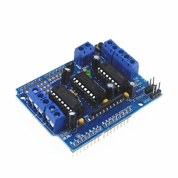
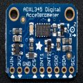
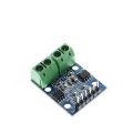
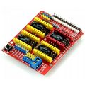
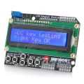
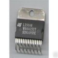
شیلد موتور درایور L293D
۹۵,۰۰۰ تومان
درایور موتور برای آردوینو L293
براي سفارش تعداد بالاي محصول و استعلام قيمت با شماره هاي فروشگاه تماس بگيريد يا در تلگرام با ما در تماس باشيد
ناموجود
درایور موتور برای آردوینو
پورت های سروو موتور ۲ و ۵ ولت (سروو) با تایمر با دقت بالا با وضوح بالا آردوینو – بدون جرقه؛ حداکثر چهار موتور دو طرفه DC و ۴ کانال PWM سرعت (حدود ۰٫۵٪ رزولوشن)؛ حداکثر ۲ کنترل حرکت پله، کنترل تک / دو مرحله ای، گام و گام گام و کنترل زاویه چرخش. چهار کاناله H پل: تراشه L293D در هر جاده و پل برای ارائه ۰۶/۰ A (پیک ۱٫۲A) جریان و با قدرت حرارتی
حفاظت، ۴٫۵V تا ۳۶V؛ مقاومت کششی برای اطمینان از اینکه موتور بر روی قدرت متوقف می شود؛ ترمینال ترمینال arge را آسان تر سیم (۱۰ – ۲۲AWG) و قدرت؛ با دکمه تنظیم مجدد Arduino؛ ترمینال خارجی منبع تغذیه ۲ ترمینال برای اطمینان از جدایی از منطق و قدرت درایو موتور؛ سازگار با مگا، Diecimila، و Duemilanove. دانلود سریع آسان برای استفاده از Arduino کتابخانه نرم افزار سریع
ارائه انواع طیف وسیعی از لوازم یدکی برای علاقه مندان به انجام DIY
نمونه کد راه اندازی شیلد
طرح زیر یک طرح ساده برای استفاده از موتور سپر بدون کتابخانه Adafruit است. این کد از موتورهای پله پشتیبانی نمی کند، اما هر خروجی نیز می تواند برای رانندگی solenoids یا رله استفاده شود.
کدها از کد آردوینو تا حد امکان استفاده می کند.
// Simple Motor Shield sketch
// ———————————–
//
// By arduino.cc user “Krodal”.
// June 2012
// Open Source / Public Domain
//
// Using Arduino 1.0.1
//
// A simple sketch for the motor shield,
// without using the Adafruit library.
//
// The outputs can be used for DC-motors
// (either full H-bridge or just On and Off), lights,
// relays, solenoids, etc.
// But stepper motors can not be used !
// Servo motors can be used with the default Servo library.
//
// A maximum of 4 DC motors can be used with full-bridge,
// or a maximum of 8 normal outputs, or a combination.
// Two servo motors can always be used, they use the +5V
// of the Arduino board, so the voltage regulator could
// get hot.
//
// Tested with an Ebay clone with the Arduino Uno.
//
// Parts of the code are from an old Adafruit Motor Shield
// library, which was public domain at that time.
// This code is also public domain
//
// This simplified program is using the normal
// Arduino library functions as much as possible.
//
// The motors will make a whistling sound,
// due to the analogWrite() PWM frequency.
// The Adafruit library is specifically designed to avoid
// this, so use the Adafruit library for a better result.
//
//
//
// Connector usage
// —————
// The order is different than what you would expect.
// If the Arduino (Uno) board is held with the USB
// connector to the left, the positive (A) side is
// at the top (north), and the negative (B) side is
// the bottom (south) for both headers.
//
// Connector X1:
// M1 on outside = MOTOR1_A (+) north
// M1 on inside = MOTOR1_B (-)
// middle = GND
// M2 on inside = MOTOR2_A (+)
// M2 on outside = MOTOR2_B (-) south
//
// Connector X2:
// M3 on outside = MOTOR3_B (-) south
// M3 on inside = MOTOR3_A (+)
// middle = GND
// M4 on inside = MOTOR4_B (-)
// M4 on outside = MOTOR4_A (+) north
//
//
// ——————————-
// | -+s |
// | -+s |
// M1 A | | M4 A
// M1 B | | M4 B
// GND | | GND
// M2 A | | M3 A
// M2 B | | M3 B
// | ….. |
// ——————————-
// + –
//
//
//
// Pin usage with the Motorshield
// —————————————
// Analog pins: not used at all
// A0 … A5 are still available
// They all can also be used as digital pins.
// Also I2C (A4=SDA and A5=SCL) can be used.
// These pins have a breadboard area on the shield.
// Digital pins: used: 3,4,5,6,7,8,9,10,11,12
// Pin 9 and 10 are only used for the servo motors.
// Already in use: 0 (RX) and 1 (TX).
// Unused: 2,13
// Pin 2 has an soldering hole on the board,
// easy to connect a wire.
// Pin 13 is also connected to the system led.
// I2C is possible, but SPI is not possible since
// those pins are used.
//
#include <Servo.h>
// Arduino pins for the shift register
#define MOTORLATCH 12
#define MOTORCLK 4
#define MOTORENABLE 7
#define MOTORDATA 8
// ۸-bit bus after the 74HC595 shift register
// (not Arduino pins)
// These are used to set the direction of the bridge driver.
#define MOTOR1_A 2
#define MOTOR1_B 3
#define MOTOR2_A 1
#define MOTOR2_B 4
#define MOTOR3_A 5
#define MOTOR3_B 7
#define MOTOR4_A 0
#define MOTOR4_B 6
// Arduino pins for the PWM signals.
#define MOTOR1_PWM 11
#define MOTOR2_PWM 3
#define MOTOR3_PWM 6
#define MOTOR4_PWM 5
#define SERVO1_PWM 10
#define SERVO2_PWM 9
// Codes for the motor function.
#define FORWARD 1
#define BACKWARD 2
#define BRAKE 3
#define RELEASE 4
// Declare classes for Servo connectors of the MotorShield.
Servo servo_1;
Servo servo_2;
void setup()
{
Serial.begin(9600);
Serial.println(“Simple Motor Shield sketch”);
// Use the default “Servo” library of Arduino.
// Attach the pin number to the servo library.
// This might also set the servo in the middle position.
servo_1.attach(SERVO1_PWM);
servo_2.attach(SERVO2_PWM);
}
void loop()
{
// Suppose there are two servo motors connected.
// Let them move 180 degrees.
servo_1.write(0);
delay(1000);
servo_1.write(180);
delay(2000);
servo_2.write(0);
delay(1000);
servo_2.write(180);
delay(2000);
// Suppose there is a relay, or light or solenoid
// connected to M3_A and GND.
// Note that the ‘speed’ (the PWM, the intensity)
// is for both M3_A and M3_B.
// The output is a push-pull output (half bridge),
// so it can also be used to drive something low.
// The ‘speed’ (the PWM, the intensity) can be set
// to zero, that would make the output disabled
// and floating.
motor_output(MOTOR3_A, HIGH, ۲۵۵);
delay(2000);
motor_output(MOTOR3_A, LOW, ۲۵۵);
// Suppose a DC motor is connected to M1_A(+) and M1_B(-)
// Let it run full speed forward and half speed backward.
// If ‘BRAKE’ or ‘RELEASE’ is used, the ‘speed’ parameter
// is ignored.
motor(1, FORWARD, ۲۵۵);
delay(2000);
// Be friendly to the motor: stop it before reverse.
motor(1, RELEASE, ۰);
delay(500);
motor(1, BACKWARD, ۱۲۸);
delay(2000);
motor(1, RELEASE, ۰);
}
// Initializing
// ————
// There is no initialization function.
//
// The shiftWrite() has an automatic initializing.
// The PWM outputs are floating during startup,
// that’s okay for the Motor Shield, it stays off.
// Using analogWrite() without pinMode() is valid.
//
// ———————————
// motor
//
// Select the motor (1-4), the command,
// and the speed (0-255).
// The commands are: FORWARD, BACKWARD, BRAKE, RELEASE.
//
void motor(int nMotor, int command, int speed)
{
int motorA, motorB;
if (nMotor >= ۱ && nMotor <= ۴)
{
switch (nMotor)
{
case ۱:
motorA = MOTOR1_A;
motorB = MOTOR1_B;
break;
case ۲:
motorA = MOTOR2_A;
motorB = MOTOR2_B;
break;
case ۳:
motorA = MOTOR3_A;
motorB = MOTOR3_B;
break;
case ۴:
motorA = MOTOR4_A;
motorB = MOTOR4_B;
break;
default:
break;
}
switch (command)
{
case FORWARD:
motor_output (motorA, HIGH, speed);
motor_output (motorB, LOW, –۱); // -۱: no PWM set
break;
case BACKWARD:
motor_output (motorA, LOW, speed);
motor_output (motorB, HIGH, –۱); // -۱: no PWM set
break;
case BRAKE:
// The AdaFruit library didn’t implement a brake.
// The L293D motor driver ic doesn’t have a good
// brake anyway.
// It uses transistors inside, and not mosfets.
// Some use a software break, by using a short
// reverse voltage.
// This brake will try to brake, by enabling
// the output and by pulling both outputs to ground.
// But it isn’t a good break.
motor_output (motorA, LOW, ۲۵۵); // ۲۵۵: fully on.
motor_output (motorB, LOW, –۱); // -۱: no PWM set
break;
case RELEASE:
motor_output (motorA, LOW, ۰); // ۰: output floating.
motor_output (motorB, LOW, –۱); // -۱: no PWM set
break;
default:
break;
}
}
}
// ———————————
// motor_output
//
// The function motor_ouput uses the motor driver to
// drive normal outputs like lights, relays, solenoids,
// DC motors (but not in reverse).
//
// It is also used as an internal helper function
// for the motor() function.
//
// The high_low variable should be set ‘HIGH’
// to drive lights, etc.
// It can be set ‘LOW’, to switch it off,
// but also a ‘speed’ of 0 will switch it off.
//
// The ‘speed’ sets the PWM for 0…255, and is for
// both pins of the motor output.
// For example, if motor 3 side ‘A’ is used to for a
// dimmed light at 50% (speed is 128), also the
// motor 3 side ‘B’ output will be dimmed for 50%.
// Set to 0 for completelty off (high impedance).
// Set to 255 for fully on.
// Special settings for the PWM speed:
// Set to -1 for not setting the PWM at all.
//
void motor_output (int output, int high_low, int speed)
{
int motorPWM;
switch (output)
{
case MOTOR1_A:
case MOTOR1_B:
motorPWM = MOTOR1_PWM;
break;
case MOTOR2_A:
case MOTOR2_B:
motorPWM = MOTOR2_PWM;
break;
case MOTOR3_A:
case MOTOR3_B:
motorPWM = MOTOR3_PWM;
break;
case MOTOR4_A:
case MOTOR4_B:
motorPWM = MOTOR4_PWM;
break;
default:
// Use speed as error flag, -3333 = invalid output.
speed = –۳۳۳۳;
break;
}
if (speed != –۳۳۳۳)
{
// Set the direction with the shift register
// on the MotorShield, even if the speed = -1.
// In that case the direction will be set, but
// not the PWM.
shiftWrite(output, high_low);
// set PWM only if it is valid
if (speed >= ۰ && speed <= ۲۵۵)
{
analogWrite(motorPWM, speed);
}
}
}
// ———————————
// shiftWrite
//
// The parameters are just like digitalWrite().
//
// The output is the pin 0…7 (the pin behind
// the shift register).
// The second parameter is HIGH or LOW.
//
// There is no initialization function.
// Initialization is automatically done at the first
// time it is used.
//
void shiftWrite(int output, int high_low)
{
static int latch_copy;
static int shift_register_initialized = false;
// Do the initialization on the fly,
// at the first time it is used.
if (!shift_register_initialized)
{
// Set pins for shift register to output
pinMode(MOTORLATCH, OUTPUT);
pinMode(MOTORENABLE, OUTPUT);
pinMode(MOTORDATA, OUTPUT);
pinMode(MOTORCLK, OUTPUT);
// Set pins for shift register to default value (low);
digitalWrite(MOTORDATA, LOW);
digitalWrite(MOTORLATCH, LOW);
digitalWrite(MOTORCLK, LOW);
// Enable the shift register, set Enable pin Low.
digitalWrite(MOTORENABLE, LOW);
// start with all outputs (of the shift register) low
latch_copy = ۰;
shift_register_initialized = true;
}
// The defines HIGH and LOW are 1 and 0.
// So this is valid.
bitWrite(latch_copy, output, high_low);
// Use the default Arduino ‘shiftOut()’ function to
// shift the bits with the MOTORCLK as clock pulse.
// The 74HC595 shiftregister wants the MSB first.
// After that, generate a latch pulse with MOTORLATCH.
shiftOut(MOTORDATA, MOTORCLK, MSBFIRST, latch_copy);
delayMicroseconds(5); // For safety, not really needed.
digitalWrite(MOTORLATCH, HIGH);
delayMicroseconds(5); // For safety, not really needed.
digitalWrite(MOTORLATCH, LOW);
}
Warning: call_user_func() expects parameter 1 to be a valid callback, no array or string given in /home/h97380/domains/tejaratelec.com/public_html/wp-content/themes/revo/woocommerce/single-product/tabs/tabs.php on line 60

